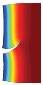
Physically, initialization of crack surface is the initialization of new free surface in the solid body, forming a geometrical discontinuity.
A numerical model that attempts to simulate cracks as discontinuity is classified as a “sharp crack model”. There are two approaches in “sharp crack” model: directly introduce crack as geometric discontinuity (see Figure 1), or mathematically describe the behavior of cracks without introduction of geometric discontinuity. In a direct model of crack growth, the problem domain is updated during crack propagation), hence it is termed as a “moving boundary problem”. Updating of the problem domain means that the discretization (e.g. the element mesh in finite element method – FEM) has to be updated accordingly (i.e. re-meshing), which is not a trivial task in practice.
Figure 1. Crack opening
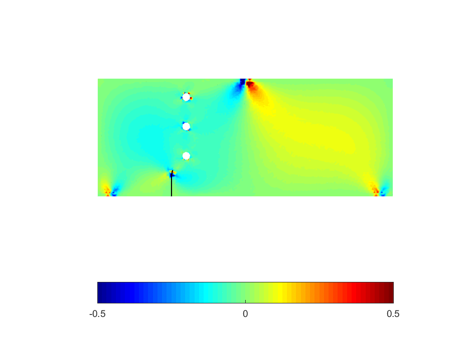
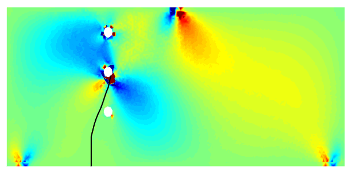
On the other hand, the mathematical description of crack tries to capture the jump in displacement across the crack surface and the singularity of stress fields in the vicinity of crack tip by insertion of mathematical functions into a known numerical scheme (e.g., finite element method, isogeometric analysis, etc.), namely enriched functions. By doing so, the burdensome re-meshing task can be avoided. In the literatures, the application of enriched functions into the traditional FEM is called by Extended FEM, or shortly XFEM [1]. An illustration of crack propagation obtained by XFEM is given in Figure 2.
It should be noted that, a fine mesh in region surrounding the crack may be required in order to get good results, regardless FEM or XFEM is used.
Reference
[1] N. Moes and J. Dolbow and T. Belytschko (1999). A finite element method for crack growth without remeshing. International Journal for Numerical Methods in Engineering 46 (1), pp. 131-150. Link